Welcome: Hangzhou Volison Technology Co., Ltd.
Language:
 ∷
∷

∷
 ∷
∷

Product introduction
Function
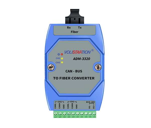
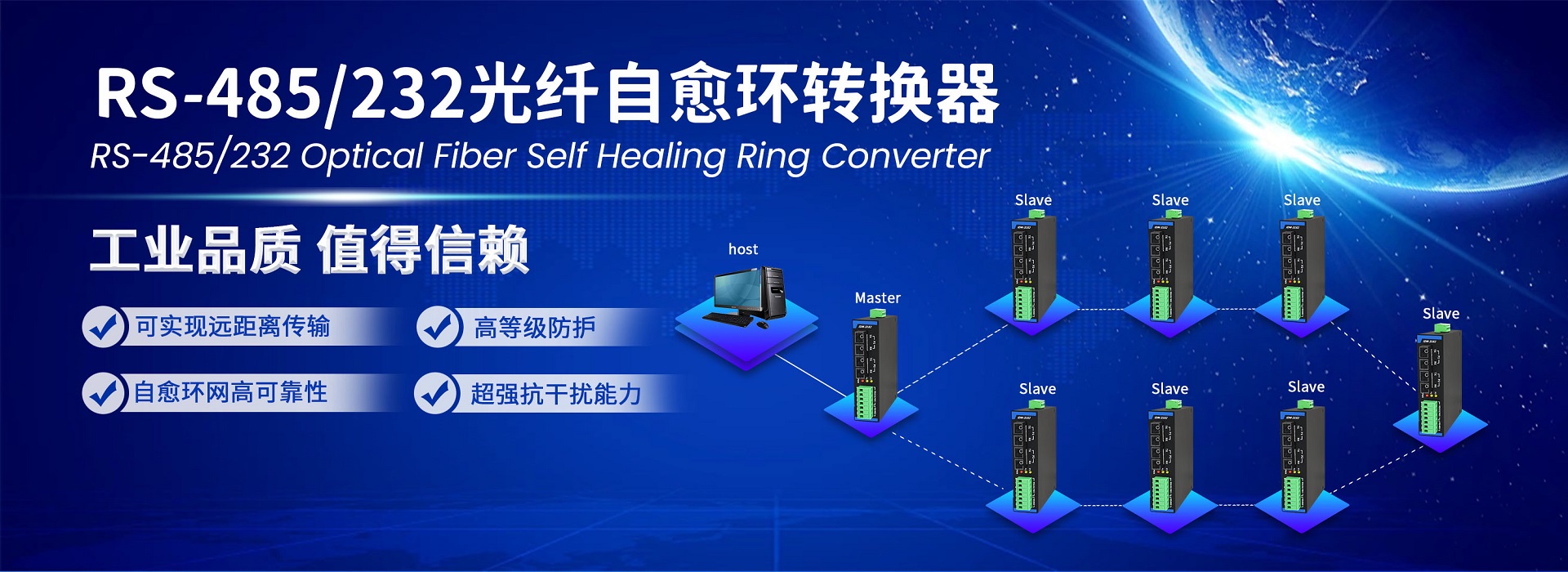
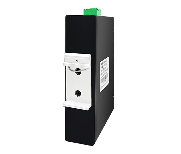
IDM-3362 is a 2-channel CAN-bus optical fiber self-healing ring converter, which can build a ring self-healing optical fiber network, greatly improving the stability of CAN bus devices using optical fiber communication.
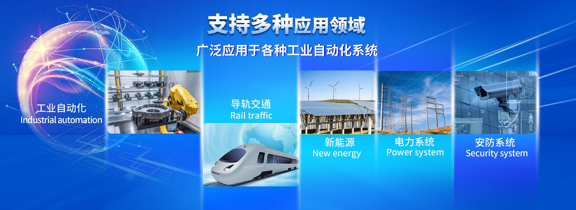
Application
IDM-3362 is suitable for optical fiber networking of fire fighting host and optical fiber communication of industrial devices. For example, IDM-3362 can be used when the fire fighting host distributed in different areas is connected with optical fiber. The device can also be used as an optical fiber repeater. Fiber optic links are used as buses, connecting all nodes in different span areas to the bus network.
Theory
When a segment of fiber is broken or a node fails, the device automatically switches the optical fiber channel, making the network still working, the communication link is unblocked, and the safety and reliability of the optical fiber communication network is greatly improved.
Regulation
IDM-3362 provides 2-channel CAN port, and the maximum speed of CAN-BUS can is up to 125kbps. 2-channel can bus device allows both sides to communicate. Each idm-3362 can be set to work in master mode or slave mode through dial switch, but only one master station is allowed in the fiber ring, and the rest is used as slave station. A fiber ring network can access up to 20 IDM-3362.
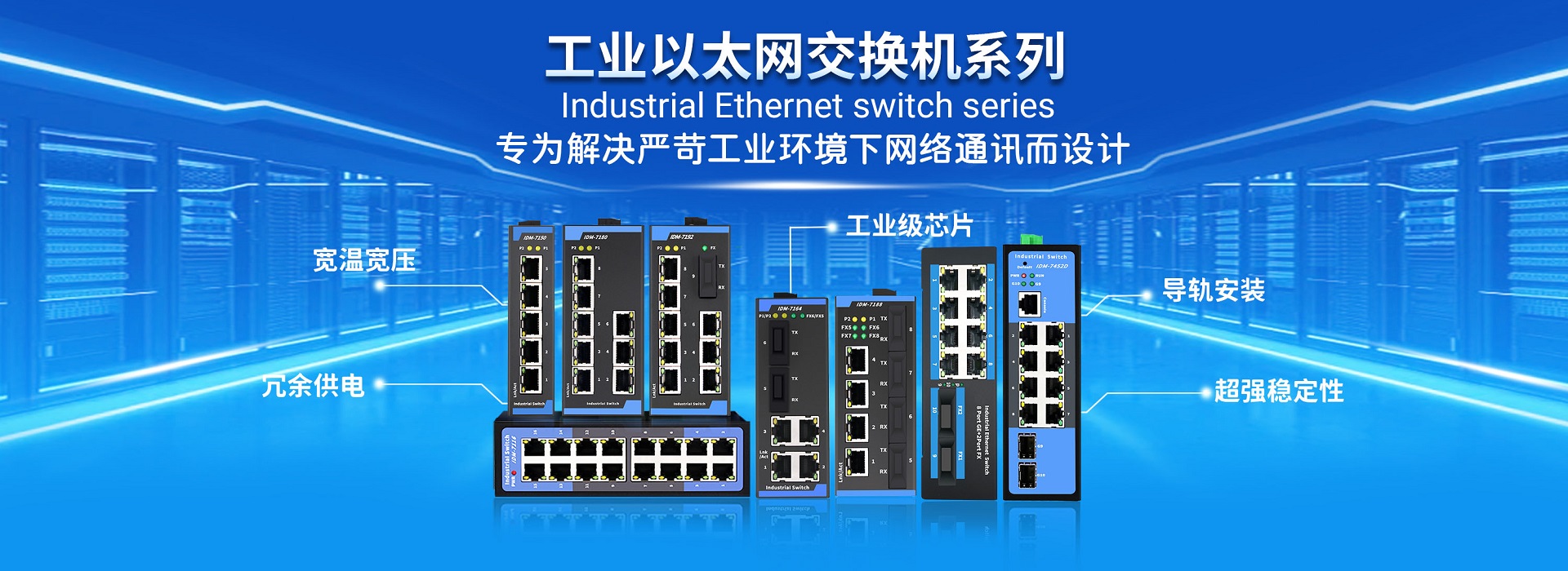
Product features
1. Point to point, point to multipoint, ring network communication mode
2. 2 - Channel optical fiber port is connected to the self-healing ring optical fiber network, and each optical fiber interface can choose single fiber or dual fiber, and SC / St / FC can choose
3. 2 - Channel can bus interface, up to 125Kbps
4. Up to 20 IDM-3362 devices can be connected to each fiber ring network
5. CAN bus baud rate self-adaption, transparent transmission
6. Master-slave mode, one master station mode in the ring network, and other work in slave mode.
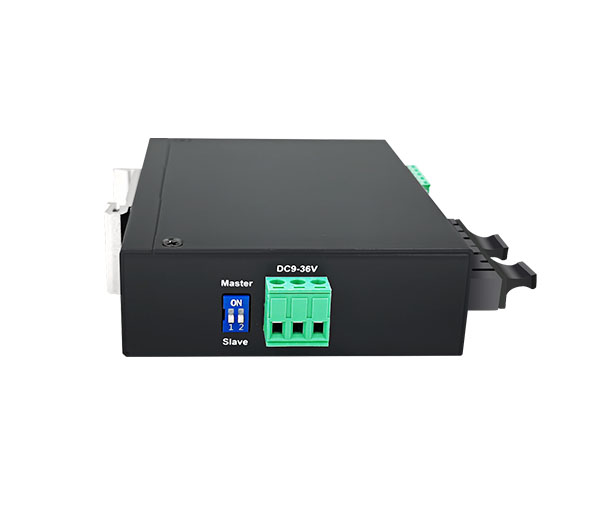
7. Industrial design, DC9~36V power supply, DIN guide rail installation
Product specification
CAN port
CAN bus port: 2Channel CAN bus
Communication rate: 5K~125Kbps
Interface definition: L, H
Connection mode: 5 PIN terminal connection
Fiber optic port
Optical fiber port: 2 Channel optical fiber port, single or multi-mode SC/ST/FC interface optional, default (SC double fiber)
Wavelength: 1310nm (Double fiber), 1310/1550 (Single fiber)
Transmission distance: multimode2 Km, single mode10 km
Power and LED instructions
LED indicator: power indicator, Fiber port 1 and 2 communication instructions
Power supply voltage: DC9~36V/400mA, less than 3W
Power connection mode: 3 Terminal Connection
Work environment
Working temperature: -20 C~ +70 C
Storage temperature: -40 C~85 C
Relative humidity: 5% to 95% non condensation
Installation
Installation: DIN rail guide
Size (W x H x L): 40mmX120mmX90mm
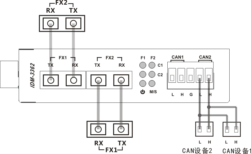
Interface definition
|
Power Supply |
DC9-36V VS+: Power positive, VS-: Power negative |
|
CAN 1 |
Channel 1: L, H |
|
CAN 2 |
Channel 2: L, H |
|
Optical Port |
FX1: Connect to the next devices FX2 FX2: Connect to the previous devices FX1 |
|
LED indicator |
PWR: Power Supply instructions M/S: Master station and Slave station instructions F1: FX1OpticalPortcommunication instructions F2: FX2OpticalPortcommunication instructions |
Installation
1. Before accessing the power supply, the main station dial switch is set to "master" and the slave station is "Slave".
2. Fiber port FX1 is connected to the FX2 fiber port of the next device, and the FX1 LED is extinguished after the fiber connection.
3. Fiber port FX2 is connected to the FX1 fiber port of the previous device, and after the fiber connection, the FX2 LED is extinguished.
4. Double-fiber devices cross-connect TX to RX and RX to TX, and single-fiber devices FX1 directly to FX2.
5. The main station uses CAN port 1, the slave station should also use CAN port 1, the main station should use CAN port 2, and the slave station should also use CAN port 2.
Model definition
IDM-3362-SC Double fiber SC interface, single mode fiber and multimode fiber
IDM-3362-FC Double fiber FC interface, single mode fiber and multimode fiber
IDM-3362-ST Double fiber ST interface, single mode fiber and multimode fiber
IDM-3362-SC1 Single fiber SC interface, only using single-mode fiber
IDM-3362-FC1 Single fiber FC interface, only using single-mode fiber
Contact: Ms Liao(Sales) / Email: liao.yanping@st-inno.com
Phone: 155-5805-0803
Tel: 400-1011-310
Email: liuchangshandx@126.com (Technical support)
Add: room 401, building D, No. 16, Xiang Mao Road, Hangzhou, Zhejiang, Gongshu District